Edupanda » Strength of materials »  Bending » Transverse Bending

List of examples

Example 1

free
todo-card-img

Freely supported beam with a cross-section shown in the figure below is loaded with a force P=100 kN. Check the stress values at critical points of the dangerous section. Apply the HMH hypothesis in the calculations. Create charts of bending moments and transverse forces, as well as stress distribution along the height of the section. The permissible stresses are: \(k_r=120\ MPa, k_c=80\ MPa\).

Example 2

todo-card-img

The freely supported beam with the cross-section shown in the image below is loaded with a force of 30 kN. Perform a chart of bending moments and shear forces, as well as a distribution of stresses along the height of the section.

Example 3

todo-card-img

An freely supported beam with the cross-section shown in the diagram below is symmetrically loaded with concentrated forces and continuous loading. Create diagrams of bending moments and shear forces, as well as stress distribution along the height of the cross-section.

Example 4

todo-card-img

The freely supported beam with the cross section shown in the diagram below is subjected to continuous loading. Plot the bending moment and shear force diagrams, as well as the stress distribution along the height and width of the section.

Example 5

todo-card-img

Given is a cross-section of a beam loaded with shear force Qz=60 kN. Calculate the shear stresses at point K of the cross-section.

Example 6

todo-card-img

The freely supported beam with the cross-section shown in the drawing below is loaded with continuous loading. For the beam cross-section with the highest shear force, plot stress distribution diagrams along the height of the cross-section.

Example 7

todo-card-img

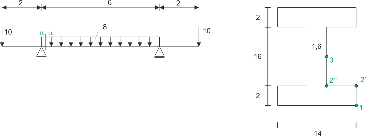
To determine the values of bending and shear stresses at the indicated points in the cross-section as shown in the drawing, and to draw stress diagrams, assuming that the bending moment in this section is M=5kNm, and the shear force is T=100kN.

Example 8

todo-card-img

To determine the values of bending and shear stresses at the marked points in the cross-section shown in the diagram, and to plot the stress diagrams, given that the bending moment in the cross-section is M=5kNm, and the shear force is T=100kN.

Example 9

todo-card-img

One-sidedly supported beam with a rectangular cross-section is loaded at the end with force P. Find the ratio of the maximum normal stress in the critical section to the maximum shear stress.

Example 10

todo-card-img

Welded I-beam shown in the picture is subjected to a cutting force T = 40 kN. Knowing the permissible stresses for the weld material kt = 80 MPa, calculate: a) the minimum thickness a1 of continuous welds. b) the pitch t of the welds if their thickness is a = 5 mm and the length l = 50 mm.

Example 11

todo-card-img

Calculate /(Σ_{extr}, \tau_{extr}/).