EduPanda Logo
  • Online Courses
    • Electrical Engineering / Circuit Theory
    • Technical Mechanics
    • Structural Mechanics / Construction
    • Fluid Mechanics
    • Numerical / Computational Methods
    • Robot Structural Analysis
    • Strength of Materials
    • Glossary of Terms
  • Calculators
  • Pricing
    /
    /
    /
footer-logo
media-instmedia-youtubemedia-fb

© 2024 EduPanda. All rights reserved.

Online Courses

  • Electrical Engineering / Circuit Theory
  • Technical Mechanics
  • Structural Mechanics / Construction
  • Fluid Mechanics
  • Numerical / Computational Methods
  • Robot Structural Analysis
  • Strength of Materials
  • Glossary of Terms
Calculators
Formulas, Charts and Tables
Shop
Sitemap
media-instmedia-youtubemedia-fb

© 2024 EduPanda. All rights reserved.

Bending

Oblique Bending

  1. Edupanda
  2. /
  3. Strength of materials
  4. /
  5. Bending
  6. /
  7. Oblique Bending

Example 1

free
Example 1

The rectangular cross-sectioned cantilever beam is loaded at the end with a force P = 10.0 kN inclined at an angle α = 30° to the vertical axis (see the drawing next to it). Determine the distribution of normal stresses in the support section and the position of the neutral axis. Design the beam's cross-section if the allowable stresses are σ = 150 MPa.

View example →

Example 2

Example 2

The cantilever beam with a rectangular cross-section is subjected to a force P = 20.0 kN at its end, inclined at an angle α = 30° to the vertical axis (see the diagram next to it). Determine the normal stresses at the characteristic points of the fastening section and the equation of the neutral axis.

View example →

Example 3

Example 3

A rectangular cross-section support beam is loaded with a continuous load inclined at an angle α = 45° to the vertical axis (as shown in the figure next to it). Determine the normal stresses at the characteristic points of the fixing section and the equation of the neutral axis. Draw a stress diagram.

View example →

Example 4

Example 4

The supporting beam with a cross-sectional profile of I-beam IPN200 is loaded with a concentrated force inclined at an angle α = 30° to the vertical axis (as shown in the adjacent figure). Determine the normal stresses at point A of the fastening section.

View example →

Example 5

Example 5

The supporting beam with a cross-section of IPE300 I-beam is loaded with a concentrated force inclined at an angle α = 45° to the vertical axis (as shown in the adjacent figure). Determine the allowable force P, if the bending strength is kg = 200 MPa.

View example →

Example 6

Example 6

Draw the My bending moment diagram for the beam shown in the image, and then for the section where the largest moment is formed, determine the position of the neutral axis and the value of the largest moment.

View example →

Example 7

Example 7

Draw a moment diagram My for the beam shown in the figure, and then for the cross-section where the largest moment occurs, prepare a stress solid.

View example →

Example 8

Example 8

Draw a My moment diagram for the beam shown in the figure, and then for the section where the largest moment is created, determine the position of the neutral axis and the value of the largest moment, create a stress block.

View example →

Example 9

Example 9

Determine the minimum dimension \(a\) [mm] of the cross-section for the given Gerber beam, assuming the allowable stresses \(R = 200\,\text{MPa}\).

View example →

Example 10

Example 10

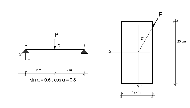
On the right side of the given beam subjected to bending diagonally in the C cross-section: write the equation of the neutral axis and draw it in the cross-section, prepare a graph of normal stresses, determine the deflection arrow and show its direction in the cross-section, calculate the extreme value of shear stresses. In the calculations, assume: \( E = 10 \ \text{GPa} \quad \text{i} \quad P = 20 + 10x \ [\text{kN}] \).

View example →