Solution
 work-obciazenia-mechaniczne/przyklad-01/new01/rys0_ynuxnk.png)
|
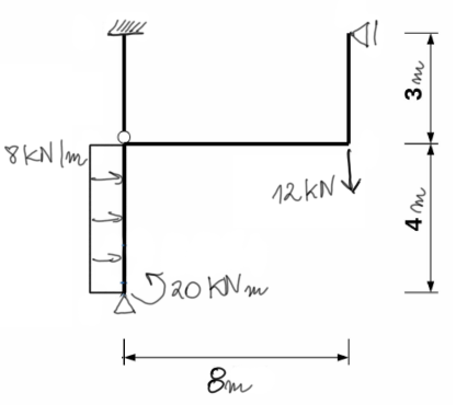
We calculate the degree of static indeterminacy (SSI) and select the basic system of the method of forces (BSMF). SSN=6-3-1=2In terms of the degree of static indeterminacy, this example is somewhatspecific, because we have two vertical reactions along the bar AC. Thus, it is an axial indeterminacy, which we cannot solve using the method of forces, but we will solve it only at the stage of calculating normal forces from the geometric condition. Nevertheless, we will solve this system as doubly indeterminate, however, as we will soon see, one unit state will turn out to be zero, so it is as if we were calculating the system with SSN=1. |
BSMF
 work-obciazenia-mechaniczne/przyklad-01/new01/rys1_lrqgac.png)
We draw unit diagrams and the diagram from the external load.
State X1=1
 work-obciazenia-mechaniczne/przyklad-01/new01/rys2_unqisj.png)
State X2=1
 work-obciazenia-mechaniczne/przyklad-01/new01/rys3_qwj5zs.png)
State P
 work-obciazenia-mechaniczne/przyklad-01/new01/rys4_o6ydqj.png)
If you have trouble drawing Moment diagrams, we encourage you to check out this video course (CLICK)
We calculate the coefficients and free terms of the canonical equation of the method of forces
More information on integration can be found in our Theoretical Introduction on this topic\begin{aligned} & \delta_{11}=\frac{1}{\mathrm{EI}} \cdot(0) \\ & \delta_{22}=\frac{1}{\mathrm{EI}} \cdot\left(\frac{1}{3} \cdot \frac{12}{7} \cdot \frac{12}{7} \cdot 4+\frac{12}{7} \cdot \frac{12}{7} \cdot 8+\frac{1}{3} \cdot \frac{12}{7} \cdot \frac{12}{7} \cdot 3+\frac{1}{3} \cdot 3 \cdot 3 \cdot 3\right)=\frac{1929}{49} \frac{1}{\mathrm{EI}} \\ & \delta_{12}=\frac{1}{\mathrm{EI}} \cdot(0) \quad \delta_{21}=\delta_{12} \\ & \Delta_{1P}=\frac{1}{\mathrm{EI}} \cdot(0) \\ \end{aligned}
 work-obciazenia-mechaniczne/przyklad-01/new01/rys5_mgwr0p.png)
\begin{aligned} & \Delta_{2 P}=\frac{1}{\mathrm{EI}} \cdot\left(\frac{1}{3} \cdot \frac{12}{7} \cdot 4 \cdot 36+\frac{1}{6} \cdot \frac{12}{7} \cdot 4 \cdot 20-\frac{1}{3} \cdot \frac{12}{7} \cdot 4 \cdot 16+\frac{1}{2} \cdot \frac{12}{7} \cdot 8 \cdot 36-\frac{1}{2} \cdot \frac{12}{7} \cdot 8 \cdot 60-\frac{1}{3} \cdot \frac{12}{7} \cdot 3 \cdot 60\right) \\ & \Delta_{2 P}=-\frac{1392}{7} \frac{1}{\mathrm{EI}} \end{aligned}
We solve the system of canonical equations and calculate X1 and X2.
\begin{aligned} &\delta_{11}\cdot{x_1}+\delta_{12}\cdot{x_2}+\delta_{1P}=0 \\ &\delta_{21}\cdot{x_1}+\delta_{22}\cdot{x_2}+\delta_{2P}=0 \\ \end{aligned} \begin{aligned} & \left\{\begin{array}{l} 0 \cdot x_1+0 \cdot x_2+0=0 \\ 0 \cdot x_1+\frac{1929}{49 EI} \cdot x_2-\frac{1392}{7 EI}=0 \end{array}\right. \\ & \left\{\begin{array}{l} 0=0 \\ x_2=5,05 \mathrm{kN} \end{array}\right. \end{aligned}We calculate the final Moment from the superposition formula
\begin{aligned} &M_{OST}=M_P+M_1\cdot{X_1}+M_2\cdot{X_2}\\ \end{aligned} We sum the diagrams work-obciazenia-mechaniczne/przyklad-01/new01/rys6_wiau5b.png)
Bridge Diagram
 work-obciazenia-mechaniczne/przyklad-01/new01/rys7_bobjco.png)
Calculations for the shear force diagram
 work-obciazenia-mechaniczne/przyklad-01/new01/rys8_mdeadv.png
)
|
\begin{aligned}
& \Sigma M_A=0 \\
& -20+44,657+8 \cdot 4 \cdot 2+ \\
& +Q_B \cdot 4=0 \\
& Q_B=-22,164 \mathrm{kN} \\
& \Sigma x=0 \\
& Q_B+8 \cdot 4-Q_A=0 \\
& Q_A=9,836 \mathrm{kN}
\end{aligned}
The extremum on the Moment diagram \begin{aligned} \frac{9,836}{x} & =\frac{22,164}{4-x} \\ x & =1,23 \mathrm{~m} \end{aligned} \begin{aligned} \text { Mex }=-20+Q_A \cdot x-8 \cdot \frac{x^2}{2}=-13,953 \mathrm{kNm} \end{aligned} |
 work-obciazenia-mechaniczne/przyklad-01/new01/rys9_ztndlz.png
)
\begin{aligned} & \Sigma M_B=0 \\ & Q_C \cdot 3+15,15=0 \\ & Q_C=-5,05 \mathrm{kN} \\ & \Sigma X=0 \\ & Q_B=Q_C \end{aligned} |
 work-obciazenia-mechaniczne/przyklad-01/new01/rys10_gt74yk.png
)
\begin{aligned} & \Sigma M_B=0 \\ & -44,657-51,343+ \\ & +Q_D \cdot 8=0 \\ & Q_D=12 \mathrm{kN} \\ & \Sigma y=0 \\ & Q_B=Q_D \end{aligned} |
 work-obciazenia-mechaniczne/przyklad-01/new01/rys11_lckoan.png
)
\begin{aligned} & \Sigma M_D=0 \\ & 51,343+Q_E \cdot 3=0 \\ & Q_E=-17,114 \mathrm{kN} \\ & \Sigma x=0 \\ & Q_D=Q_E \end{aligned} |
Shear Force Diagram
 work-obciazenia-mechaniczne/przyklad-01/new01/rys12_gyxi64.png)
Calculations for the normal force diagram
Node B work-obciazenia-mechaniczne/przyklad-01/new01/rys13_ciswig.png) \begin{aligned} & \Sigma x=0 \\ & -5,05+22,164+ \\ & +N_{B D}=0 \\ & N_{B D}=-17,114 \mathrm{kN} \\ & \sum y=0 \\ & N_{B C}-12-N_{A B}=0 \\ & * N_{B C}=12+N_{A B} \\ \end{aligned} here we have that axial indeterminacy that we mentioned at the beginning |
Node D work-obciazenia-mechaniczne/przyklad-01/new01/rys14_by2stu.png) \begin{gathered} \sum x=0(\text { spr.) } \\ -N_{B D}-17,114=0 \\ 0=0 \\ \Sigma y=0 \\ 12+N_{D E}-12=0 \\ N_{D E}=0 \mathrm{kN} \end{gathered} |
Solution of axial indeterminacy (geometric condition)
The shear force of 12kN and its direction tells us in which direction node B will move, and thus which bar will be in tension and which will be in compression.The elongation of bar BC is equal to the shortening of bar AB - and that is the geometric condition.
Let us recall the formula for elongation/shortening of a bar: \( \Delta_L = \frac{N\cdot L}{EA} \)
 work-obciazenia-mechaniczne/przyklad-01/new01/rys15_yqfgqs.png)
|
\begin{aligned} & \Delta L_{A B}=\Delta L_{B C} \\ & \frac{-N_{A B} \cdot 4}{E A}=\frac{N_{B C} \cdot 3}{E A} \\ & -4 N_{A B}=3 N_{B C} \\ & N_{A B}=-0,75 N_{B C} \\ & * N_{B C}=12-0,75 N_{B C} \\ & \left\{\begin{array}{l} N_{B C}=6,857 \mathrm{kN} \\ N_{A B}=-5,143 \mathrm{kN} \end{array}\right. \\ & \end{aligned} |
Final normal force diagram
 work-obciazenia-mechaniczne/przyklad-01/new01/rys16_clzief.png)
Kinematic check
\( \delta_i=\int \frac{Most \cdot \overline{M_i}}{EI} d S=0 \) work-obciazenia-mechaniczne/przyklad-01/new01/rys17_ve42pf.png)
\begin{aligned} & \delta_2=\frac{1}{\mathrm{EI}} \cdot\left(\begin{array}{l} \frac{1}{3} \cdot 3 \cdot 3 \cdot 15 \cdot 15+\frac{1}{3} \cdot \frac{12}{7} \cdot 4 \cdot 44.657+\frac{1}{6} \cdot \frac{12}{7} \cdot 4 \cdot 20-\frac{1}{3} \cdot \frac{12}{7} \cdot 4 \cdot 16+\frac{1}{2} \cdot \frac{12}{7} \cdot 8 \cdot 44.657- \\ -\frac{1}{2} \cdot \frac{12}{7} \cdot 8 \cdot 51.343-\frac{1}{3} \cdot \frac{12}{7} \cdot 3 \cdot 51.343 \end{array}\right) \\ & \delta_2=-0.055 \frac{1}{\mathrm{EI}} \end{aligned} Relative error
\( \left|\frac{\delta_2}{\Delta_{2 p}}\right|=0.027 \% \quad<1,5 \% \)
Static check
We read the reactions (values and correct directions) from the diagrams of normal forces, shear forces, and bending moments.Then we write the equations of static equilibrium and check if all equations are satisfied for the read reactions.
 work-obciazenia-mechaniczne/przyklad-01/new01/rys18_vgdmbs.png) \begin{aligned}
& \Sigma \mathrm{x}=0 \\
& -5.05-17.114+8 \cdot 4-9.836=-0 \\
& \Sigma \mathrm{y}=0 \\
& 5.143+6.857-12=0 \\
& \Sigma \mathrm{M}_{\mathrm{D}}=0 \\
& -17.114 \cdot 3-5.05 \cdot 3+6.857 \cdot 8+15.15-8 \cdot 4 \cdot 2+9.836 \cdot 4+5.143 \cdot 8-20=0.002 \sim 0
\end{aligned}
\begin{aligned}
& \Sigma \mathrm{x}=0 \\
& -5.05-17.114+8 \cdot 4-9.836=-0 \\
& \Sigma \mathrm{y}=0 \\
& 5.143+6.857-12=0 \\
& \Sigma \mathrm{M}_{\mathrm{D}}=0 \\
& -17.114 \cdot 3-5.05 \cdot 3+6.857 \cdot 8+15.15-8 \cdot 4 \cdot 2+9.836 \cdot 4+5.143 \cdot 8-20=0.002 \sim 0
\end{aligned}
If you have any questions, comments, or think you have found a mistake in this solution, please send us a message at kontakt@edupanda.pl.