Solution
See more about integrating with the Wereszczagin method.
Exercise solution:
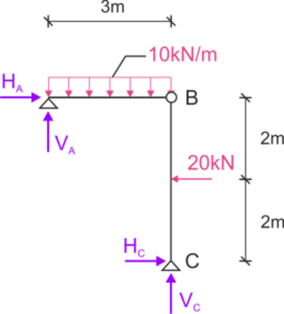
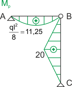
To calculate the sought displacements, we need to plot the bending moment diagram from the external load (initial load).

Bending moment diagram from the external load
\begin{aligned} \\ \sum&{{M_B^P}}=0 & &20\cdot 2-H_C\cdot 4=0 & &H_C;=10 kN\\ \sum&{X}=0 & &H_C;+H_A-20=0 & &H_A=10 kN\\ \sum&{M_C}=0 & &V_A\cdot 3-10\cdot3\cdot \frac{3}{2}=0 & &V_A=15 kN\\ \sum&{Y}=0 & &V_A+V_C-10\cdot 3=0 & &V_C=15 kN\\ \\ \end{aligned}
Rotation angle change at node B
To calculate the rotation angle change at node B (hinge), we apply a generalized force corresponding to this displacement - which is an equivalent moment from both sides of the hinge (opposite directions). The sought displacement is the integral of the bending moment diagram from the initial and virtual loads on corresponding members.


Rotation angle at node A
This time, if we are looking for the rotation angle at node A, the generalized force corresponding to this displacement is a concentrated moment applied at point A.


