
Solution
Calculation of the torque according to the formula \(M_s=9550\cdot \frac{N [kW]}{n [rpm]} M_s=9550\cdot \frac{10}{955}=100 Nm\)
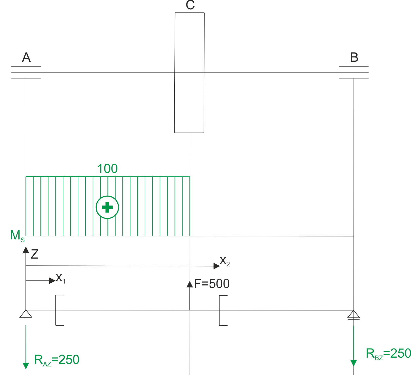
The force F on the arm of half of the pulley absorbs the torque that is imparted by the engine at the beginning of the shaft. The torque is created between the engine and the pulley. We calculate the force F on the pulley.
\begin{aligned} &F\cdot 0.2=100\Rightarrow F=500 N\\ \end{aligned}We are dealing with shaft bending in one plane and torsion.
Torque diagram and schematic for calculating bending moment.
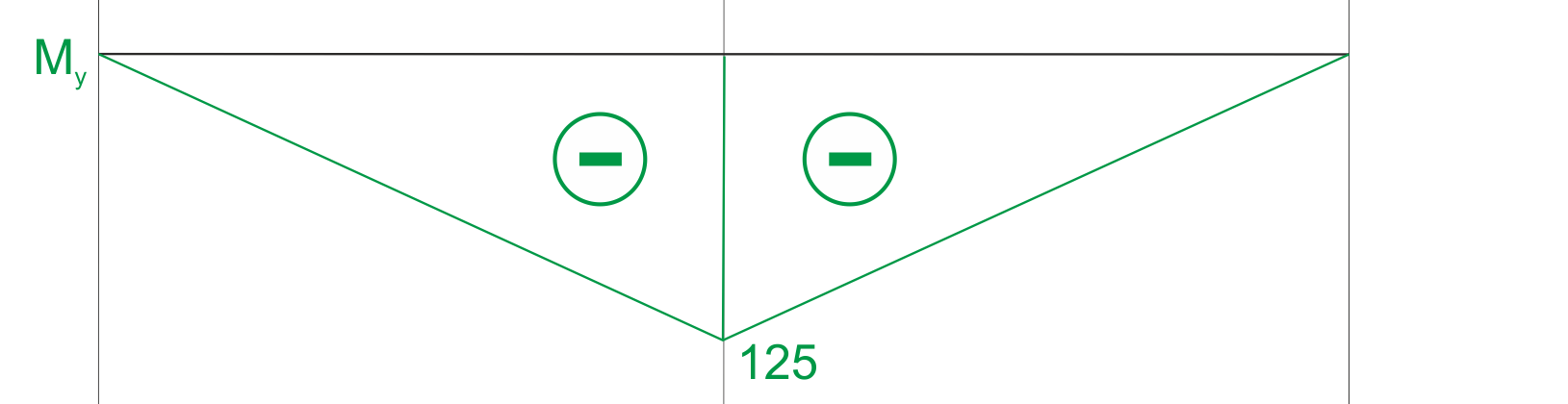
 \begin{aligned}
&x_{1} \in(0 ; 0.5) \\
&M\left(x_{1}\right)=-R_{A Z} \cdot x_{1} \\
&M(0)=0 N m \\
&M(0.5)=-125 N m \\
&x_{2} \in(0.5 ; 1) \\
&M\left(x_{1}\right)=-R_{A Z} \cdot x_{2}+500 \cdot\left(x_{2}-0.5\right) \\
&M(0.5)=-125 N m \\
&M(1)=0 N m
\end{aligned}
\begin{aligned}
&x_{1} \in(0 ; 0.5) \\
&M\left(x_{1}\right)=-R_{A Z} \cdot x_{1} \\
&M(0)=0 N m \\
&M(0.5)=-125 N m \\
&x_{2} \in(0.5 ; 1) \\
&M\left(x_{1}\right)=-R_{A Z} \cdot x_{2}+500 \cdot\left(x_{2}-0.5\right) \\
&M(0.5)=-125 N m \\
&M(1)=0 N m
\end{aligned}
Bending moment diagram.
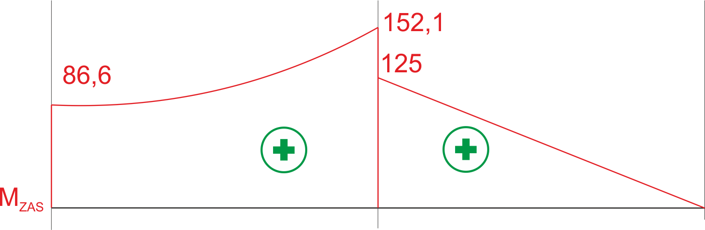
We calculate the value of the equivalent moment at characteristic points.
\begin{aligned} &M_{z a s}=\sqrt{M_{g}^{2}+\frac{3}{4} M_{s}^{2}} \\ &M_{z a s}^{A}=\sqrt{0^{2}+\frac{3}{4} \cdot 100^{2}}=86.6 \mathrm{Nm} \\ &M_{z a s}^{C A}=\sqrt{125^{2}+\frac{3}{4} \cdot 100^{2}}=152.1 \mathrm{Nm} \\ &M_{z a s}^{C B}=\sqrt{125^{2}+\frac{3}{4} \cdot 0^{2}}=125 \mathrm{Nm} \\ &M_{z a s}^{B}=\sqrt{0^{2}+\frac{3}{4} \cdot 0^{2}}=0 \mathrm{Nm} \end{aligned}Equivalent moment diagram.
We dimension the shaft for the maximum equivalent moment. We use the derived formula
\begin{aligned} &M_{z a s}^{\max }=152.1 \mathrm{Nm} \\ &d \geq \sqrt[3]{\frac{32 M_{z a s}}{\pi \cdot k_{g}}} \\ &d \geq 0.0295 \mathrm{~m} \\ &d=3 \mathrm{~cm} \end{aligned}
If you have any questions, comments, or think you have found a mistake in this solution, please send us a message at kontakt@edupanda.pl.