Edupanda » Strength of Materials » Twisting of Circular Bars
Twisting of Circular Bars
- when we deal with twisting
- how the twisting moment can be represented
- about the convention of positive sign for the twisting moment
- what is and what is the formula for:
a) twist angle
b) torsional moment of inertia for circular and annular sections
c) unit twist angle
d) deformation torsion angle
e) shear stresses
f) torsional strength index
- what is the form of stress and strain tensor for a twisted rod
- how to calculate the elastic energy for a twisted rod
- how the stress cube and Mohr's circle look like for pure shear case
You will also find calculation examples and
↓ a link to a database with exercises with solutions and to video courses ↓
Watch a video course from this section!
(statically determinate twisting)
Watch a video course from this section!
(statically indeterminate twisting)
See exercises from this section!
(statically determinate twisting)
See exercises from this section!
(statically indeterminate twisting)
When do we deal with twisting?
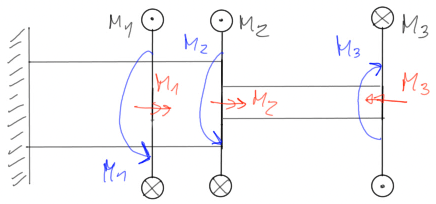
We deal with twisting when the system of external forces reduces to a twisting moment (i.e. a moment whose vector is parallel to the longitudinal axis of the bar, i.e. perpendicular to the cross-section). In this theoretical introduction, we will focus on the twisting of circular bars, which is a special case of twisting that applies the Bernoulli's plane sections principle, which states that a flat section perpendicular to the axis of the bar remains flat and perpendicular to the deformed axis after deformation.The twisting moment can be represented in three ways:


Fig1. Methods of representing the twisting moment
Convention of positive sign for the twisting moment

Fig2. Convention of positive sign for the twisting moment
Assuming:
- the material of the bar is linearly elastic with material constants E and v,
- small displacements,
- the use of Bernoulli's plane sections,
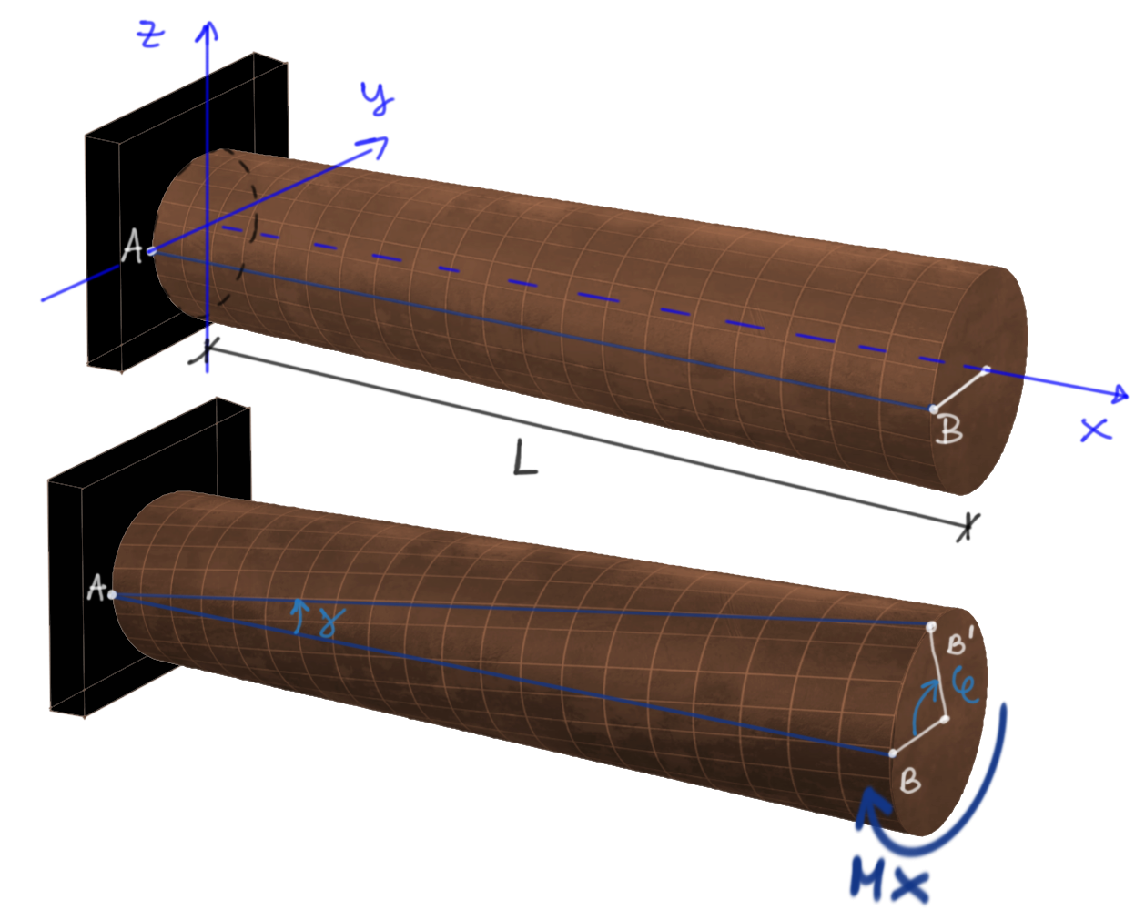
we can assume the deformation pattern as shown in figure 3 below.
Let's analyze the movement of line AB before and after the application of the twisting moment.
Fig3. Picture of the rotation of a circular bar

\(\boldsymbol{\varphi}\) - twist angle at the end section
\(\boldsymbol{\gamma}\) - deformation torsion angle
\(\boldsymbol{\theta}\) - twist angle per unit length
Twist angle at the end section is calculated using the formula:
\begin{aligned} &\varphi=\frac{\mathrm{M}_{\mathrm{x}} \cdot \mathrm{L}}{\mathrm{G} \cdot \mathrm{I}_s}\\ \end{aligned} If the bar was loaded with a continuous, rather than concentrated, twisting moment, then we must use this version of the formula: \begin{aligned} &\varphi=\int_{x_p}^{x_k} \frac{M_x(x)}{G \cdot I_s} d x \end{aligned}Mx - twisting moment or Mx(x) - function of the twisting moment
L - length of the bar, or length of part of the bar
G - shear modulus (material constant)
Is - torsional moment of inertia
Torsional moment of inertia
For a circular or annular cross section, the torsional moment of inertia is equal to the polar moment of inertia. The polar moment of inertia is simply the sum of the moments of inertia about two perpendicular axes passing through the point (the pole, in this case the center of gravity) and it is simply:- for annular cross section \[ I_s=\frac{\pi \cdot\left(D^4-d^4\right)}{32} \] D - outer diameter of the annulus,
d - inner diameter of the annulus
- for circular cross section \[ I_s=\frac{\pi \cdot D^4}{32} \]
Twist angle per unit length (unit twist angle)
is calculated using the formula: \[ \theta=\frac{\mathrm{M}_{\mathrm{x}}}{\mathrm{G} \cdot \mathrm{I}_{\mathrm{s}}} \]Deformation torsion angle \( \gamma \)
The formula for the deformation torsion angle can be derived directly from Figure 3.First, we assumed at the beginning that we have small displacements, so the angle \( \gamma \) will be very small, because it is the ratio of a small arc segment to the circumference of the BB' section of the rod, which is much longer. For small angles, it is sufficient to approximate that \( \gamma = tg(\gamma) \), in other words, that the value of angle gamma is equal to its tangent.
Second, a quick reminder from mathematics - the formula for an arc segment (we are interested in the arc segment between B and B'): \[Ł=\frac{\varphi}{360^{\circ}} 2 \pi r = \varphi \cdot r\] the first form if we substitute the twist angle in degrees, the second - the one we use - if we substitute it in radians, i.e. the basic unit.
Therefore, the formula for deformation torsion angle is: \[ \gamma = \varphi \cdot r \] \[ \begin{aligned} \tau_{BC} &= \frac{M_{BC}}{W_{S}} = \frac{-20 \mathrm{kNm}}{\frac{\pi \cdot 6^3}{16}} \\ \tau_{AB} &= \frac{M_{AB}}{W_{S}} = \frac{10 \mathrm{kNm}}{\frac{\pi \cdot 6^3}{16}} \end{aligned} \end{aligned} \]
Wyznaczamy kąt skręcenia na przedziałach charakterystycznych
\begin{aligned} \varphi_{BC} &= \frac{\tau_{BC} \cdot \rho_{BC}}{G} = \frac{\frac{-20 \mathrm{kNm}}{\frac{\pi \cdot 6^3}{16}} \cdot \frac{6}{2}}{80 \text{ GPa}} \\ \varphi_{AB} &= \frac{\tau_{AB} \cdot \rho_{AB}}{G} = \frac{\frac{10 \mathrm{kNm}}{\frac{\pi \cdot 6^3}{16}} \cdot \frac{6}{2}}{80 \text{ GPa}} \end{aligned}Narysujmy wykresy

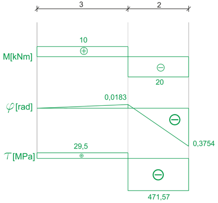
Rys9. Wykres momentów skręcających na przedziałach BC i AB

Rys10. Wykres naprężeń stycznych na przedziałach BC i AB

Rys11. Wykres kąta skręcenia na przedziałach BC i AB
In order to do this, we need to calculate the torsional strength coefficients
\begin{aligned} &W_{S_{B C}}=\frac{\pi \cdot 0,06^{3}}{16}=4.24 \cdot 10^{-5} \mathrm{~m}^{3} \\ &W_{S_{A B}}=\frac{\pi \cdot 0,12^{3}}{16}=3.39 \cdot 10^{-4} \mathrm{~m}^{3} \\ \end{aligned}Now we can calculate the stresses
\begin{aligned} &\tau=\frac{M_{B C}}{W_{S_{B C}}}=\frac{-20 \cdot 10^{3}}{4.24 \cdot 10^{-5}}=-471.57 \mathrm{MPa} \\ &\tau=\frac{M_{A B}}{W_{S_{A B}}}=\frac{10 \cdot 10^{3}}{3.39 \cdot 10^{-4}}=29.5 \mathrm{MPa} \end{aligned}Next, we will calculate the torsional angles in characteristic sections relative to the fixed point
\begin{aligned} &\varphi=\frac{M_{S} \cdot l}{G \cdot I} \\ \end{aligned}For this, we need the moments of inertia for torsion
\begin{aligned} &I=\frac{\pi \cdot d^{4}}{32} \\ &I_{B C}=\frac{\pi \cdot 0,06^{4}}{32}=1.27 \cdot 10^{-6} \mathrm{~m}^{4} \\ &I_{A B}=\frac{\pi \cdot 0,12^{4}}{32}=2.04 \cdot 10^{-5} \mathrm{~m}^{4} \\ \end{aligned}For example, the torsional angle of section C relative to section B can be calculated as follows:
\[ \varphi_{B C}=\frac{M_{S_{B C}} \cdot l_{B C}}{G \cdot I_{B C}} \]But let's start with the fixed point at point A, where we know that the rotation angle is equal to 0
\[ \varphi_{A}=0 \]Then the rotation angle of section B relative to A:
\[ \varphi_{B}=\varphi_{A}+\varphi_{A B} \]and the total torsional angle, which is the sum of the torsional angle at B and the torsional angle of section C relative to B
\[ \varphi_{C}=\varphi_{B}+\varphi_{B C} \]Calculations
\begin{aligned} &\varphi_{A B}=\frac{10 \cdot 10^{3} \cdot 3}{80 \cdot 10^{9} \cdot 2.04 \cdot 10^{-5}}=0.0183 \text{ rad} \\ &\varphi_{B C}=\frac{-20 \cdot 10^{3} \cdot 2}{80 \cdot 10^{9} \cdot 1.27 \cdot 10^{-6}}=-0.3937\text{ rad} \\ &\varphi_{B}=0+0.0183=0.0183 \text{ rad} \\ &\varphi_{C}=0.0183-0.3937=-0.3754 \text{ rad} \end{aligned}After all the calculations, we can draw graphs of torsional moments, shear stresses, and torsional angles


